 RSyntaxTree
Documentation
Table of Contents
- Basic Usage
- Tree Direction
- Fonts Used to Generate PNG
- Install Fonts for SVG
- Font Styles, Text Decoration, and Sub/Superscripts
- Triangle, Square Brackets, Rectangle
- Per-Node Styling (Color)
- Region Shade
- Escape Special Characters
- Draw Paths between Nodes (experimental)
- Draw Extra Connectors between Nodes (experimental)
- Command Line Interface Features
Basic Usage
Type your text in the editor area using labeled bracket notation and click the Draw PNG or Draw SVG button.
Every branch or leaf of the syntax tree must belong to a node. To create a node, place the label text right next to the start bracket. Any number of branches may follow, separated by a whitespace. (Node labels containing whitespaces can be created using the <> symbol. For example, Modal<>Aux will be rendered as Modal Aux).
There are three different types of connector drawn between a terminal node and its leaves (auto, bar and none). auto draws a triangle for leaves containing one or more whitespaces (= phrases). If the leaf does not contain any spaces (= single word), a straight bar is drawn instead (unless the leaf contains a ^ symbol at the beginning, which specifies the leaf to be a phrase). The connectors can be made transparent using the Hide default connectors option.
The newline character \n can be used within the text of both node lables and leaves.
RSyntaxTree can generate PNG and SVG, SVG can be used with third party vector graphics software such as Adobe Illustrator, Microsoft Visio, BOXY SVG, etc. It is very useful if you want to modify the output image.
The Radical symmetrization option affects the way branch nodes are drawn. The options Font style, Font size, Connector height, and Color need no explanation. By changing the values of these options, you can change the appearance of the resulting image.
Tree Direction
The Direction option controls the orientation of the tree layout:
- Top to Bottom (
ttb): The default. Root node at the top, leaves at the bottom. - Left to Right (
ltr): Root node at the left, leaves expand to the right. Useful for classification trees, taxonomies, and other hierarchical structures where horizontal layout is preferred.
In left-to-right mode, connectors, triangles, movement paths, and line-type connections are all adapted to the horizontal orientation. The Connector Height option controls the horizontal depth between tree levels in LTR mode.
Fonts Used to Generate PNG
Currently, you can choose among the font styles Noto Sans, Noto Serif, Noto Sans Mono and WQY Zen Hei.
Noto Sanscan display basic Unicode characters (including Japanese hiragana/katakana/kanji).Noto Serifcan display basic Unicode characters (including Japanese hiragana/katakana/kanji).WQY Zen Heican display a wide range of Chinese/Japanese/Korean (CJK) characters.Noto Sans Monocan display basic Unicode characters in a mono-spaced typeface.
Install Fonts for SVG
SVG images are dependent on the fonts installed locally on your computer. In order for the images to display as intended, the following fonts should be installed beforehand (click on the links). If these fonts are not installed, other available fonts will be used, resulting in a somewhat unbalanced display of the text.
- Noto Sans: for latin and other basic Unicode characters in sans serif
- Noto Sans JP: for Japanese characters in sans serif
- Noto Serif: for latin and other basic Unicode characters in serif
- Noto Serif JP: for Japanese characters in serif
- WQY Zen Hei: for CJK characters
- Noto Sans Mono: for latin and other basic Unicode characters in sans serif mono (semi-condensed)
- OpenMoji: for emoji characters.
Font Styles, Text Decoration, and Sub/Superscripts
You can apply font styles (italic/bold/bold-italic), text decoration (overline/underline/line-through), subscript/superscript font rendering, and more. These markups can be nested within each other.
Font Styles
| Style | Symbol | Sample Input | Output |
|---|---|---|---|
| Italic | *TEXT* |
*italic* |
italic |
| Bold | **TEXT** |
**bold** |
bold |
| Italic+bold | ***TEXT*** |
***italic bold*** |
italic bold |
Text Decoration
| Decoration | Symbol | Sample Input | Output |
|---|---|---|---|
| Overline | =TEXT= |
=overline= |
overline |
| Underline | -TEXT- |
-underline- |
underline |
| Line-through | ~TEXT~ |
~linethrough~ |
linethrough |
Note: Currently, overline is displayed in SVG, but not in PNG.
Subscript and Superscript
| Sample Input | Output |
|---|---|
normal_subscript_ |
normalsubscript |
normal__superscript__ |
normalsuperscript |
Box, Circle, Bar, and Arrow
| Sample Input | Output |
|---|---|
|| |
 |
{} |
 |
*||* |
 |
*{}* |
 |
|/| |
 |
{/} |
 |
|1| |
 |
{1} |
 |
|abc| |
 |
{abc} |
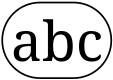 |
-- |
 |
*--* |
 |
-> |
|
*->* |
|
<- |
|
*<-* |
|
<-> |
|
*<->* |
Whitespace inside Label
| Sample Input | Output |
|---|---|
X<>Y |
X Y |
Newline
| Sample Input | Output |
|---|---|
str1\str2 |
str1 str2 |
str1\ \str2 |
str1 str2 |
str1\ str2 |
str1 str2 |
str1\ \ str2 |
str1 str2 |
str1\nstr2 |
str1 str2 |
str1\n\nstr2 |
str1 str2 |
Horizontal Line
| Sample Input | Output |
|---|---|
str1\---\str2 |
str1 —— str2 |
str1\ ---\ str2 |
str1 —— str2 |
str1\n---\nstr2 |
str1 —— str2 |
Here, --- represents - repeated three times or more consecutively.
Triangle, Square Brackets, Rectangle
In auto mode, the triangle connector shape is applied when the terminal node contains words separated by whitespace. In bar and none modes, triangles are drawn for the nodes with ^ at the beginning of the leaf text, lie [NP ^syntax-trees].
If a # character is placed at the beginning of a label or leaf text (right after ^ if there is one), the text is enclosed in a pair of square brackets (e.g. [#NP text], [NP #text], [NP ^#text]).
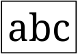
If ## is placed at the beginning of the leaf text, a rectangle is drawn instead of brackets.
If ### is placed at the beginning of the leaf text, a rectangle with thicker lines is drawn.
Per-Node Styling (Color)
You can specify a custom color for individual nodes using the @color: prefix. Both named colors and hex color codes are supported.
| Sample Input | Description |
|---|---|
@red:NP |
Named color (red) |
@blue:VP |
Named color (blue) |
@#FF5500:NP |
Hex color code |
@#0A0:VP |
Short hex color code |
Markup Order: When combining with other prefixes, use this order: ^ (triangle) → # (enclosure) → % (region shade) → @color: (color)
| Sample Input | Description |
|---|---|
^@blue:NP |
Triangle connector + blue color |
#@red:NP |
Square brackets + red color |
^#@green:NP |
Triangle + brackets + green color |
Region Shade
While #, ##, and ### enclose a single node label, a region shade paints a
semi-transparent plane behind the whole subtree that a node governs. This is
useful for marking spans such as c-command domains, binding domains, or the
dominion of a reference point in cognitive grammar.
Put a % at the beginning of a node label (after ^/# if present). The plane
covers the bounding box of that node together with all of its descendants and is
drawn behind the tree lines and labels. The shade color reuses the same
@color: syntax; % on its own uses a light gray.
| Sample Input | Description |
|---|---|
%VP |
Region shade in the default light gray |
%@yellow:VP |
Region shade in yellow (named color) |
%@#ffcc00:VP |
Region shade with a hex color |
%@yellow:@blue:VP |
Yellow shade plane and blue node label (the two colors are independent) |
Each plane is drawn with a border in a darker shade of its own fill color, so
the region stays clearly bounded even on a white background. An explicit shade
color is always honored (just like the @color: node-text color), so for a
black-and-white figure use bare % (gray) rather than a colored shade.
Overlapping or nested regions blend naturally because the planes are
semi-transparent. Region shade works in both top-to-bottom and left-to-right
(-d ltr) layouts, and applies to all raster/vector outputs (SVG, PNG, PDF,
JPG, GIF).
Escape Special Characters
The backslash character \ must be used to print certain characters used in the markup. If you do not have the \ key on your keyboard, you can also use the yen/yuan character ¥ to escape.
| Input | Appearance |
|---|---|
\[ | [ |
\] | ] |
\< | < |
\> | > |
\^ | ^ |
\+ | + |
\* | * |
\- | - |
\_ | _ |
\= | = |
\~ | ~ |
\| | | |
\% | % |
\\ | \ |
\¥ | ¥ |
<> | whitespace |
\n | ↩️ |
\↩️ | ↩️ |
\ + whitespace | ↩️ |
Note: A newline character ↩️ is treated just as a whitespace. Thus 1) \n, 2) \↩️, and 3) \ followed by a whitespace character are all rendered as a newline ↩️ in the resulting image. Note also that a ↩️ or a whitespace repeated more than once is reduced to a single whitespace.
Note: A straight ASCII apostrophe (') in a label is automatically rendered as a typographic (curly) apostrophe ’, which looks smarter in serif fonts and suits X-bar primes such as T'. This also applies to apostrophes in ordinary words (e.g. John’s).
Draw Paths between Nodes (experimental)
You can draw any number of paths of three different types:
- Non-directional (rendered as dashed line
- - -) - Directional (rendered as solid line
----▶) - Bidirectional (rendered as solid line
◀----▶)
Each path is distinguished by a unique ID number. The ID is specified by putting a plus sign and a number (e.g. +7) at the end of the node text. If a greater-than > or less-than < symbol is placed between the plus sign and the number (e.g. +>7 or +<7), an arrowhead will appear at the end of the path. Note that it makes no difference whether +> or +< is used. The arrow is always directed to the element with one of these ID symbols.
A node can have any number of IDs. The same ID must appear in the text of the two nodes between which the path is rendered. The same ID number cannot appear in more than two places.
Draw Extra Connectors between Nodes (experimental)
You can also add extra connector between nodes in the same fasion as you draw paths between nodes. Extra connectors are drawn as straigt lines (not as polylines). You may enable the Hide default connectors option when drawing extra connectors.
- Non-directional (rendered as solid line
-----) - Directional (rendered as solid line
--▶--) - Bidirectional (rendered as solid line
-◀-▶-)
Each additional connectors is distinguished by an ID number. The ID is specified by putting a a number after a sequence of a plus and a minus symbols (e.g. +-8) at the end of the node text. If a greater-than > or less-than < symbol is placed between the minus sign and the number (e.g. +->8), an arrowhead will appear at the end of the connector. Note that it makes no difference whether +-> or +-< is used. The arrow is always directed to the element with one of these ID symbols.
A node can have any number of IDs. The same ID must appear in the text of the two nodes between which the additional connector is rendered. The same ID number cannot appear in more than two places.
Command Line Interface Features
The following features are available only in the command-line interface.
Penn Treebank Format
RSyntaxTree automatically detects and converts Penn Treebank format to bracket notation:
# Penn Treebank format
(S (NP the dog) (VP runs))

# Equivalent bracket notation
[S [NP the dog] [VP runs]]
Escaping special characters in Penn Treebank format:
| Input | Displayed as |
|---|---|
\( \) |
Parentheses () as literal text |
\[ \] |
Square brackets [] as literal text |
Example:
(S (NP hello\(world\)) (VP test))
→ [S [NP hello(world)] [VP test]]
Standard Input Support
You can pipe tree data via standard input:
echo "[S [NP hello] [VP world]]" | rsyntaxtree -f svg -o ./
cat tree.txt | rsyntaxtree -f png -o ./
Configuration File
Create a .rsyntaxtreerc file in your home directory or current directory to set default options:
# ~/.rsyntaxtreerc
format: svg
color: modern
fontsize: 18
leafstyle: auto
symmetrize: off
CLI arguments override configuration file settings. Unknown options in the config file will generate warnings, and invalid values will cause errors with helpful messages.
TikZ Output
RSyntaxTree can generate TikZ/forest code for LaTeX documents using the -f tikz option. The output can be used directly in LaTeX with the forest package.
Limitations: The TikZ output focuses on tree structure and does not support the following visual features:
| Feature | TikZ Support |
|---|---|
Per-node coloring (@color:) |
Not supported |
Enclosures (#, ##) |
Not supported |
Triangle connectors (^) |
Not supported |
| Text decoration (bold, italic) | Not supported |
Subscript/superscript (_x_, __x__) |
Not supported |
Path drawing (+1, +>1) |
Not supported |
Region shade (%) |
Supported (via forest fit to=tree) |
Users familiar with LaTeX can manually add these features to the generated TikZ code using standard LaTeX commands (e.g., \textcolor{red}{NP}, \textbf{...}).
Note on region shade: The generated forest code draws each region plane on the TikZ background layer. When you embed non-standalone output in your own document, load the required libraries with \usetikzlibrary{backgrounds,fit} (the standalone output adds this automatically). Region colors (named or hex) are emitted as explicit RGB values, so SVG/CSS color names that xcolor does not define (e.g. lightblue) still compile.